By Chris Heintz, P. Eng.
[This article is part 3 of a 4-part series, where aeronautical engineer Chris Heintz discusses light aircraft airfoils.]
In Part 1 of this series, we introduced our discussion of airfoils with a study of relative flow, Reynolds numbers, boundary layers and airfoil geometry, in Part 2, we took a look at the forces acting on an airfoil - lift, drag and moment and some of the trailing edge devices used to increase lift without too much penalty in drag, moment and/or building complication. In this third part, we will try to get a better understanding of the leading edge high lift devices, boundary layer control and stall.
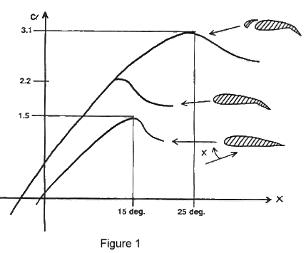
To get our discussion started, let's ask this question: why do we get the behavior shown in Figure 1; ie., why does the lift increase when we lower the flaps and increase further when we cut leading edge slots?
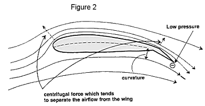
In changing from a plain airfoil to an airfoil with flaps we have created an increase of curvature of the airfoil which gives part of the extra lift, but we have also created a depression, a low pressure near the trailing edge, which sucks the air over the upper part of the airfoil and helps it to overcome the centrifugal forces present when the air flow has to come around the nose of the wing. It is like a pull acting from the trailing edge and pulling the air around the leading edge, thus preventing separation (see Figure 2).
It is obvious that by slowly increasing the angle of attack "x", there is a limit beyond which the centrifugal forces, either near the leading edge or close to the flap hinge point, can no longer be overcome by the trailing edge suction and the airfoil flies in separated air; in other words, is stalled and supplies a lower lift (see Figure 1 again).
In order to be able to further increase the lift by delaying the stall to even higher angles of attack, we have to limit the flap deflection so that the stall will first occur at the leading edge and then provide a force which neutralizes the centrifugal force. This can be done in various, more or less practical ways:
- Help the air move around the leading edge with a roller. This is very effective (CL of up to 5), but not at all practical (see Figure 3a).
- Increase the leading edge radius because the centrifugal force is proportional to 1:R, ie. by increasing R we decrease the force wanting to pull the air away from the airfoil (see Figure 3b). This is quite simple and an easy, effective "add on." The sharper the original radius, the more effective the modification will be. For example, Steve Wittman gained some 10 mph on his "Tailwind" with a "sharp" original leading edge, whereas on a Zodiac CH-600, which already had a blunt nose, the gain was negligible. Note that this "drooped" nose also increases the curvature and, unless it is movable, there will be a drag penalty in cruise (small angle of attack). Note also that this modification alters the wing chord and as a result the center of gravity range so be careful.
- Simply create a depression where required; ie., some holes through which the air is sucked inside the wing (see Figure 3C). This again is not very practical.
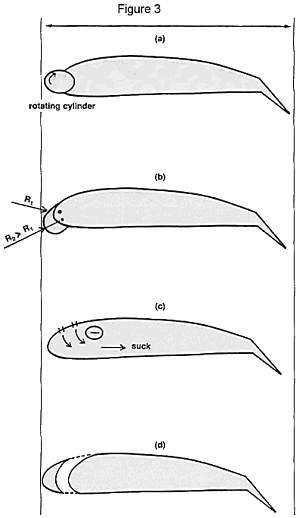
The most practical solution is to choose one area as a suction point and build the airfoil in such a way that suction can be obtained automatically (see Figure 3d). You know that when a given amount of air is accelerated (its speed increases), the pressure drops. It follows that if we guide air through a narrowing slot (a funnel) it must go faster and faster to get through and if the exit is smaller than the entrance we have a definite suction at the exit. So, if we cut a slot near the leading edge with a funnel shape and further orient the exit lips so that the fast air runs out tangent to the air foil, this will help reactivate the boundary layer and will allow us to in crease the lift on our wing up to CL equivalent to 3 to 3.1, which is over twice the original plain airfoil value of 1.5.
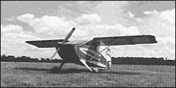 |
This photo of a Wittman Tailwind gives a good view of the sharp leading edge radius used by Steve Wittman, which increased his speed by 10 mph. (EAA file photo). |
We should also keep in mind the following:
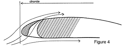
- The chord is measured from leading edge to trailing edge and the the slot is not added but the slot is cut in the airfoil; in other words, if you add the slots to an existing wing you will alter the chord and center of gravity to such an extent that you will also have to modify the tall area (which will create additional stresses in the rear fuselage). You'd be much better off to start designing a new aircraft!
- The slots can also be moved further down, thus increasing further the curvature and lift, but again this is limited by the drag increase in cruise you feel you can live with.
And, of course, you can retract the slots to minimize the drag at lower angles of attack - but you have to be aware that the construction will take longer, the aircraft will be heavier (which defeats part of the advantage) and finally, you put an additional workload on the pilot. Let's face some facts: on an average, we probably fly our airplanes 30 to 50 hours per year. Compare that to driving your car one hour every weekend; you can quickly see where you could easily become a lousy "weekend driver." If we do not want more aircraft accidents, being the "lousy weekend flyers we are," then the machines we fly must be pretty well adapted to what we can handle. But, this may not be the case anymore with an additional control . . . and to make the slots retract automatically would simply complicate the construction some more and give us gray hair before we even fly the bird. It's a lot easier to stick with something simple; that works without problems; that we can build in a reasonable amount of time and enjoy flying without special skills. That's what homebuilding is all about!
In our next installment, we will wrap up our discussion of airfoils by going over some of the high lift design features of the Zenair STOL CH 701 as related to the slotted wings.